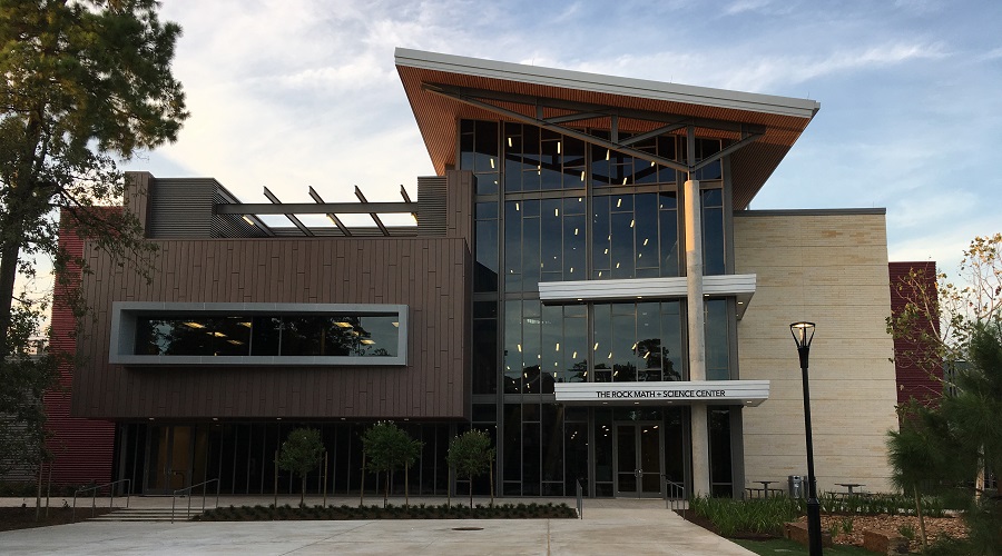
THE JOHN COOPER SCHOOL ROCK MATH AND SCIENCE CENTER

Owner: The John Cooper School
Architect: Ziegler Cooper Architects
Construction Cost: $16.9 million
Square Footage: 56,000 sq. ft.
Completed: 2016
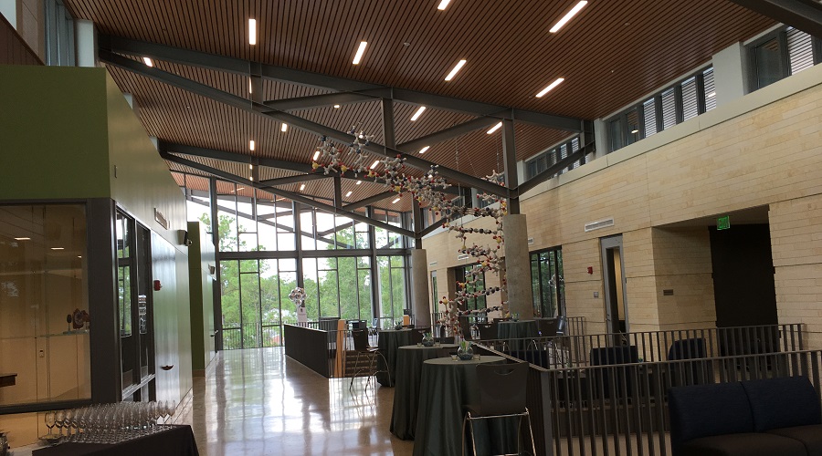
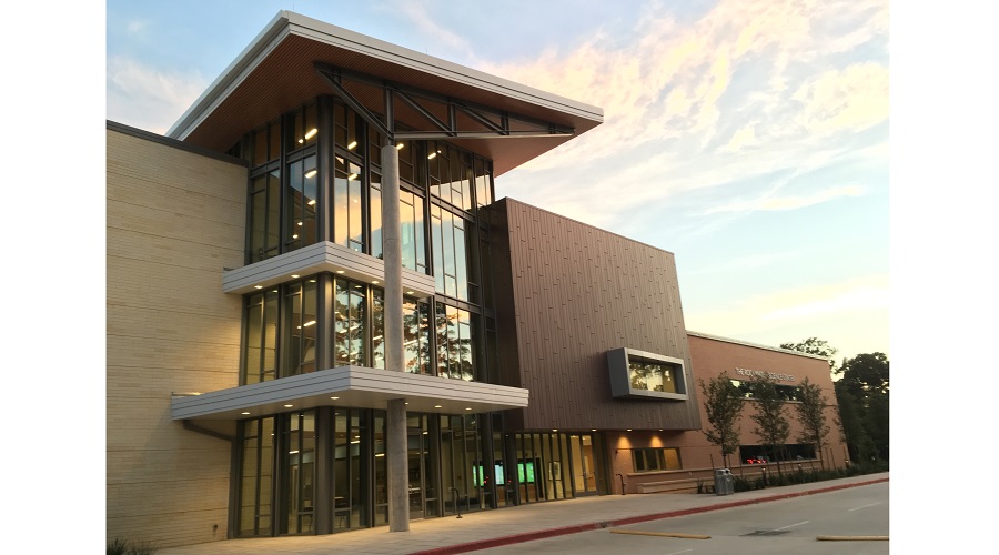
The John Cooper School Rock Math and Science Center in The Woodlands, Texas is a state-of-the-art facility designed to immerse students in STEM beyond the classroom, by exposing them to STEM concepts through the architecture itself. As students move between classrooms they are exposed to the building’s epicenter: a three-story open “forum”, concurrently connecting classrooms and being used by students as an interactive experimentation space, observable by all students throughout their day. To encourage curiosity in the built environment, the forum showcases, rather than hides, the structure. The forum roof clear spans 36 feet and is supported by six, sloping triangular trusses constructed of exposed wide flange members. Each roof truss balances on a 22 inch diameter, 40 foot tall unbraced concrete column that remains exposed through the forum space. The three-story glass walls anchoring the forum space span gracefully between exposed wide flange columns and beam supports. A series of 20 and 25 foot long cantilevered beams create the uncommon geometry of the column-free second and third-floor interactive environment.
A prime opportunity to express structural design presented itself with the monument stairs in the forum. Each stair run spans up to 35 feet horizontally between supports, and rises 14 feet in two runs with an intermediate landing. The design team contrived a way to visually convey both load-path and tension/compression members by designing each stair as a truss, using the stringers as the bottom chord, the top of the hand rail as the top chord, and combining HSS vertical web members with threaded rod diagonal members for the compression and tension elements, respectively. Not only was the result a visually stunning truss, but the application of engineering principles resulted in a stringer width that did not exceed 4-inches, and a smaller HSS stringer size.
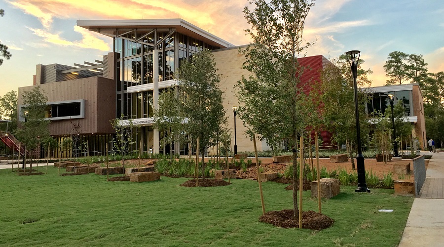
The third floor showcases a budding roof garden, artfully framed with exposed, galvanized wide flange steel members. The garden structure cantilevers 15 feet off the face of the building, connecting it seamlessly with the landscaping and open spaces of the central green space 30 feet below.
A combination of HSS diagonal braces and wide flange moment frames was used for the main wind force resisting system. To overcome the challenges of the nine different roof planes at varying elevations and slopes, as well as the lack of continuity between floor diaphragms at the forum, the engineering team analyzed semi-rigid diaphragms at both the composite floors and the roofs. By carefully assessing known assumptions for concrete cracked factors and modulus of elasticity values for untopped roof deck, PSE was able to engineer an envelope of forces at each lateral resisting element and confirm sufficient diaphragm capacity for the load transfers. In comparison to more common simplified diaphragm analyses, the in-depth semi-rigid analysis technique provided smaller moment frames and larger diagonal braces, while also reducing building drift, resulting in cost savings and a reduction in field labor and testing.
gallery